Info on some of the boats our members have built
We don't have many build logs despite a lot of people bringing boats they have built to the lake! If you want to document your build and send it over, that would be great..
Andy's Seaducer
Seaducer Build - words and pics by Andy Details of the build can also be found on the Model Boat Mayhem Forum
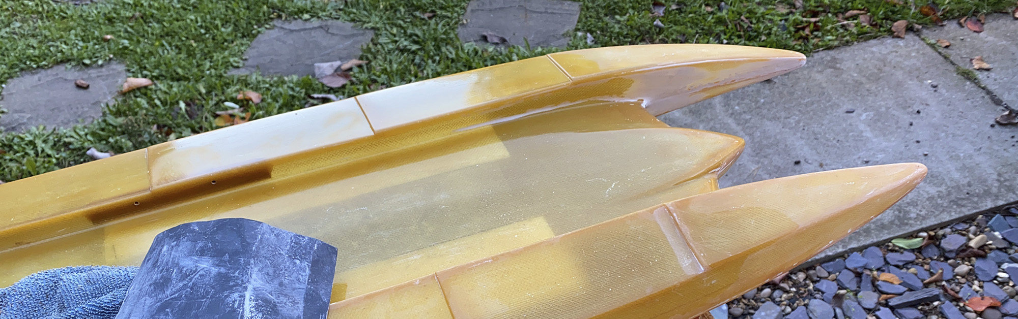
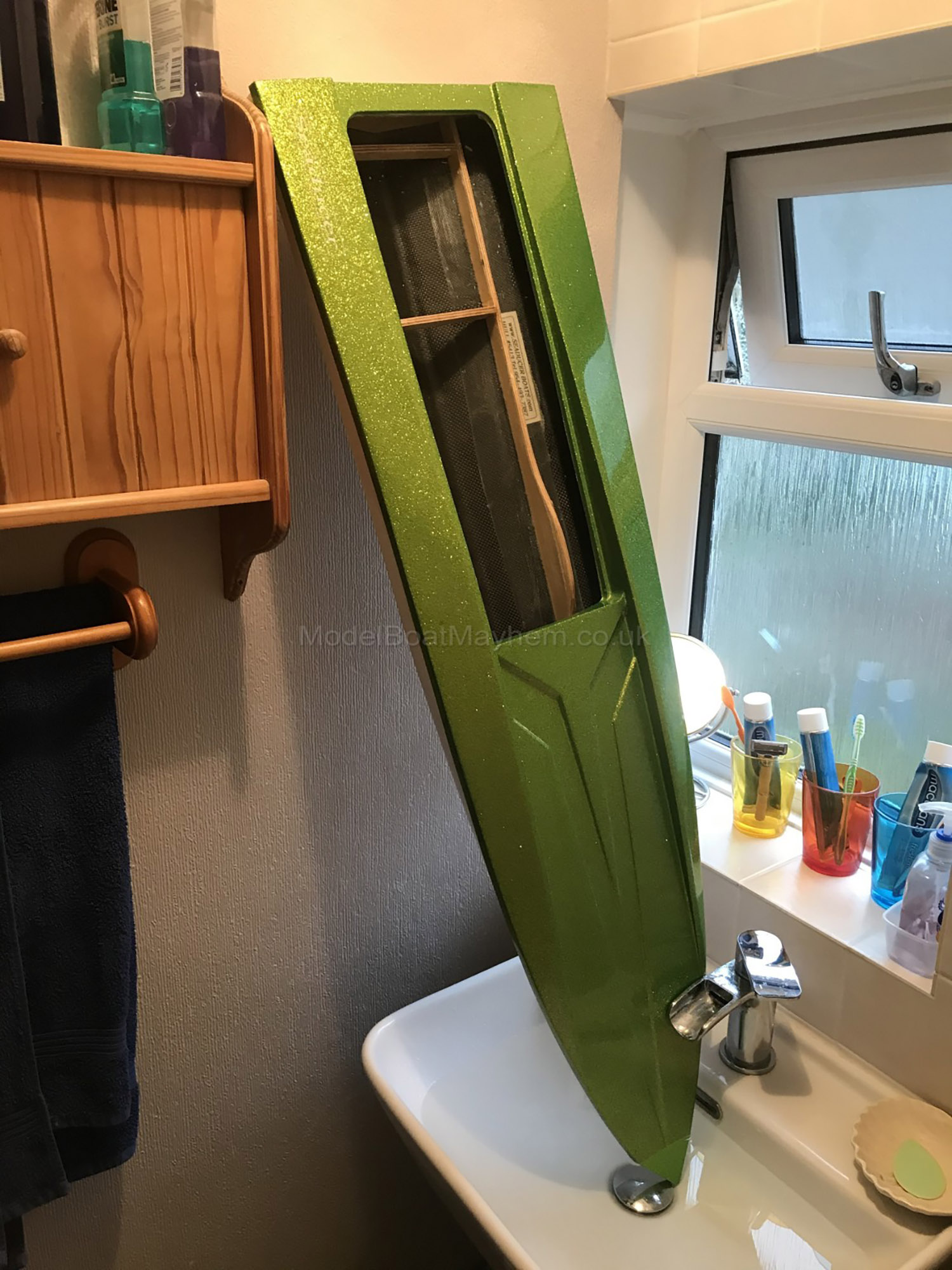
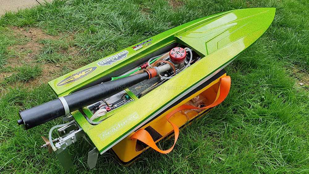
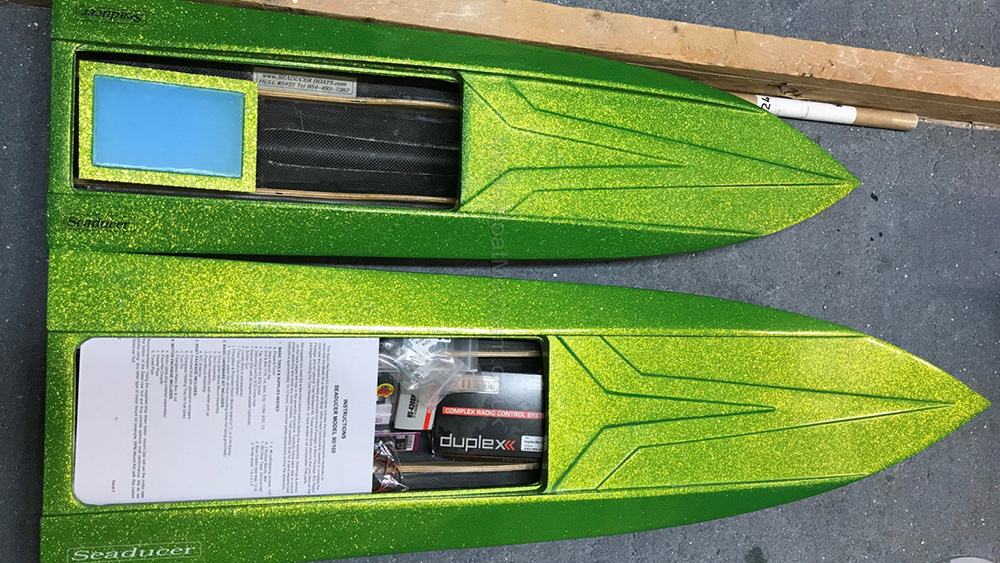
At the end of last year, I had my new hull delivered - a Seaducer 90-100 SD3. This was custom made for me by Jerry with the Gecko Green metal flake deck, with white undersides. I decided it was so impressive that I had to order the 40 boat too. Both hulls are full carbon fibre layup and vacuum bagged. This one is the newest boat designed by Jerry, measuring 45" long by 11" beam. This boat currently holds the mono speed record at 98mph, Seaducer boats have all sorts of records to their name, with various national title wins in the USA over the years.
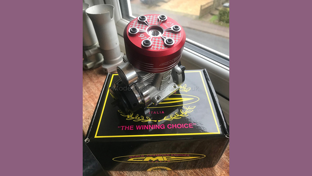
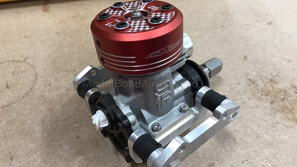
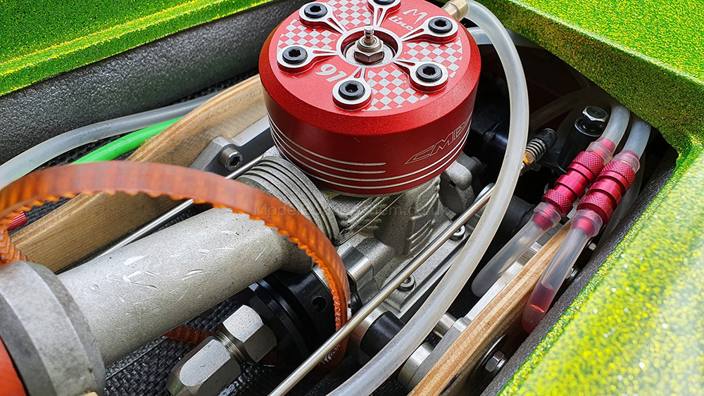
Power is provided by the new CMB 91 M-Line, which chucks out 7 horsepower at nearly 30k rpm. Prop initially started as an Octura x462 for running in, then a 465 and hopefully stepping up to a x467 when it’s fully run in. Radio is Jeti, with a Savox SB-2292SG on steering, a Savox SV-1273TG on throttle and a Hitec HS-430BH on mixture, all powered by a Hacker 2000mah 7.4v lipo.
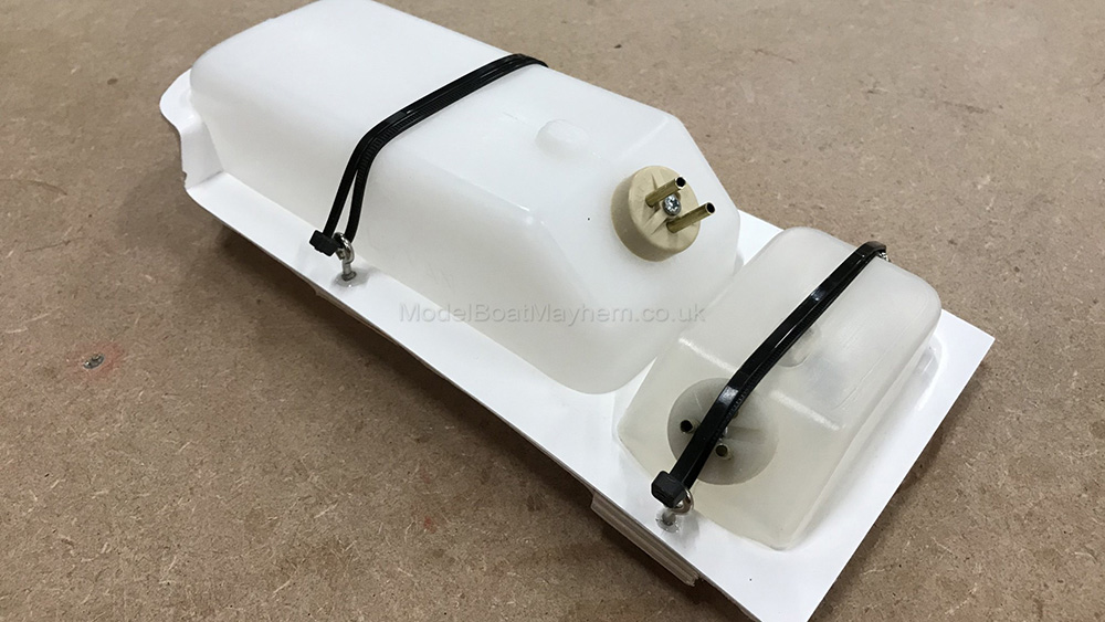
Construction started by assembling the glassfibre fuel tank tray, which just involves screwing and epoxying in some eyelets to secure cable ties to hold the tanks in place. Tanks are both Sullivan Slant types, with a 24ox main and 4oz header tank. Pipe pressure will feed into the main tank, which delivers fuel to the header to maintain a constant and consistent fuel supply to the motor. When this was all done, it was tacked into the hull with two-ton epoxy, which was strengthened further when it cured.
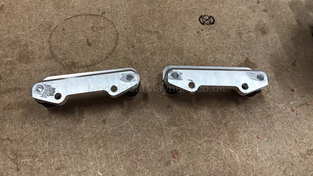
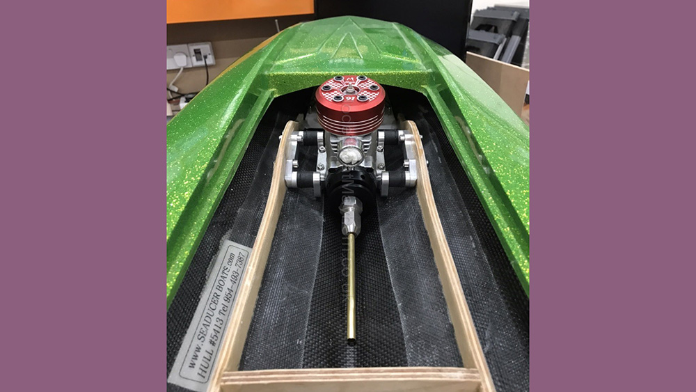
With this boat I purchased Jerry's own Seaducer hardware set, which is beautifully machined and includes the strut, rudder, drop mounts for the engine and a pipe mount. Steve (our webmaster and engineering guy) was kind enough to drill the mounts for me so I could mount the engine.
Next job - put it in the sink... Most commonly done with cat hulls but I decided to do it with this, ‘pouring the tips’ involves standing the boat on end and pouring resin into the nose, in this case 10ml of West Systems laminating resin. This helps to ensure that in the event of a collision the force will be transfer down the hull and be dissipated, rather than just breaking the nose off. Because resin gets warm and cracks when setting in large volumes, it’s best to leave it to cure in the sink or a bucket.
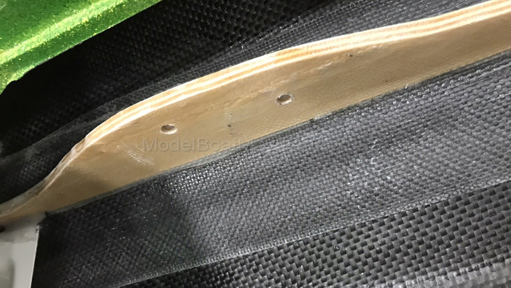
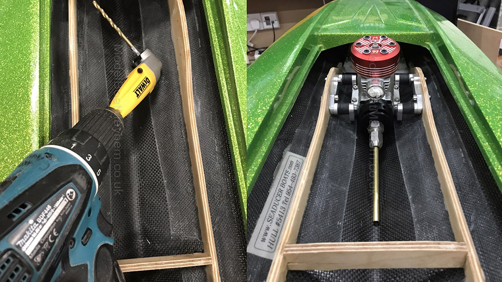
With the engine mounted, I got it into the correct position in the boat (17 inches from tip of glowplug to the inside of the transom board, with a 5" length of 1/4" brass tube in the motor’s coupling, with the end of the brass touching the bottom of the boat for the correct angle). This was then marked for drilling, having checked that the engine starter belt has got enough room to slip out when the engine has started. The drop mounts allow you to get the flywheel almost touching the bottom of the boat, so it's important to make sure you can get the belt in and out. The whole lot is secured in with M5 bolts, with penny washers outside the rails. It is important to seal the wood so any water ingress won't decay the rails over time, so I just mix and poke in 5-minute epoxy whenever I drill holes through the wood.
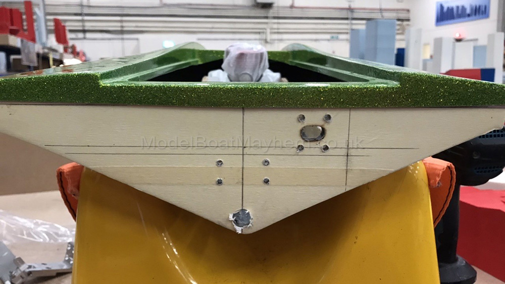
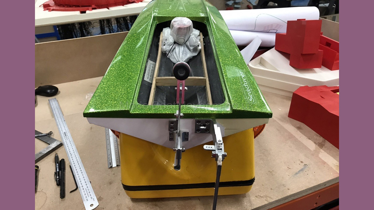
With this done, I moved on to the transom hardware. I started by masking taping the whole transom, then drawing reference lines of where everything needs to work from. I started by drilling the 1/2" free flood / drain hole around the shaft exit. From there I lined up the strut and rudder, marked and drilled for each.
My only one complaint about the Seaducer hardware pack is that the screws aren't really the highest quality, so I replaced all of it with new. Jerry's machined hardware is second to none, it's of excellent quality and the material used is very high grade. What interested me about the strut in particular is that it has a 3-degree offset machined into the leg, to counter prop effects on the boat. Clever tricks - and why everyone says that if you don't use the Seaducer hardware the boat will never run right...
Lastly for the transom hardware is the pipe mount. The kit mount wouldn’t work with the pipes I intended on using as it’s designed for the unsilenced pipes they use in the US. No bother as Prestwich Models do a 50mm pipe mount that will hold my pipe and fit onto Jerry's mount. The rudder was cut down to height, using a 24" ruler along the bottom of the hull. I marked the point where the rudder blade is in line with the hull, then a square line 3 3/4" down the blade from that point to cut the blade to.
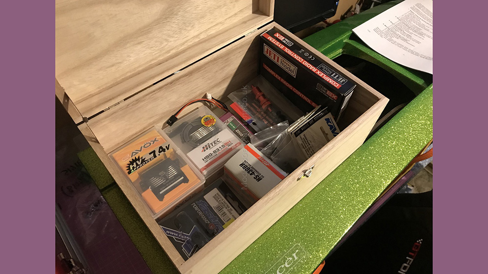
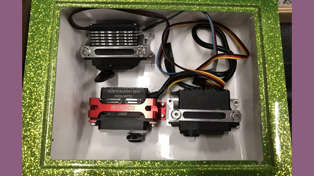
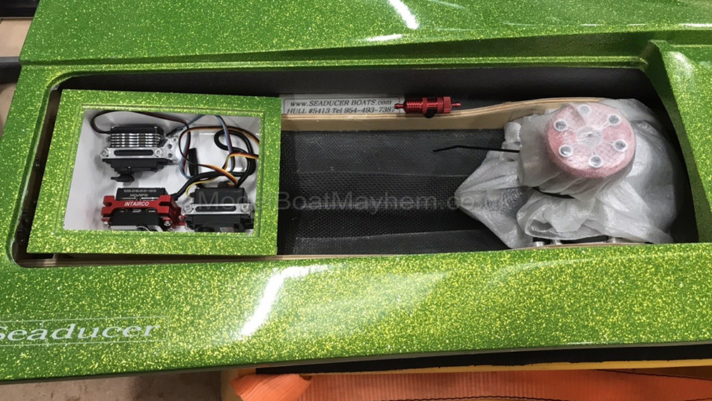
I've gone for a total deviation on the instructions in the radio box as I despise the use of wood on glassfibre in radio boxes. It never lasts and every time I’ve seen it done, things eventually peel away. I've gone for all ally mounts bolted through the bottom of the box, again with epoxied screws for water tightness. The throttle is top left of the picture, rudder bottom left and mixture bottom right. The 2000mah 7.4v Li-Po went to the top right, with the receiver on the rear wall of the box. To the right of the mixture servo I placed an Ian's Boats waterproof switch. I then fitted the pipe pressure filter / cooler, this is a unit from Answer RC that will help to reduce the amount of detritus that will find its way from the pipe into the tanks. It came with its own clip mount that is threaded underneath for M3, so I drilled and tapped the rail M3, then epoxied in a length of threaded brass bar.
Pictures from Andy's build - Click an image to view full size
Unfortunately this is where I stopped photographing the build, which can also be found here:
The build concluded by glassing in the stuffing tube for the flexi shaft using glass tape and west Systems resin, and linking the servos to their respective connections using M3 stainless rod, tapped on either end and using ball joints throughout. Below are some photos of the completed boat.
Mike's Barges
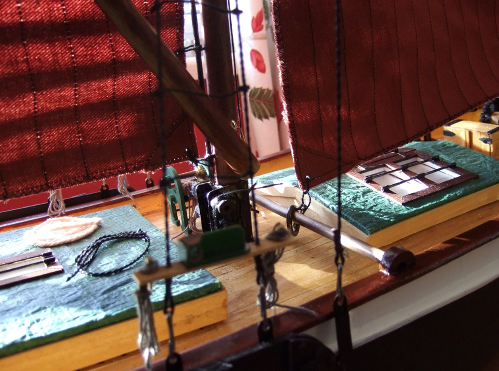
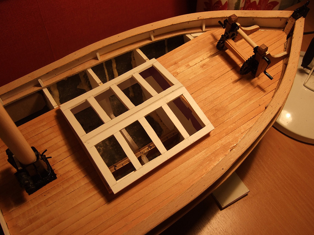
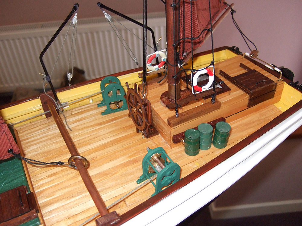
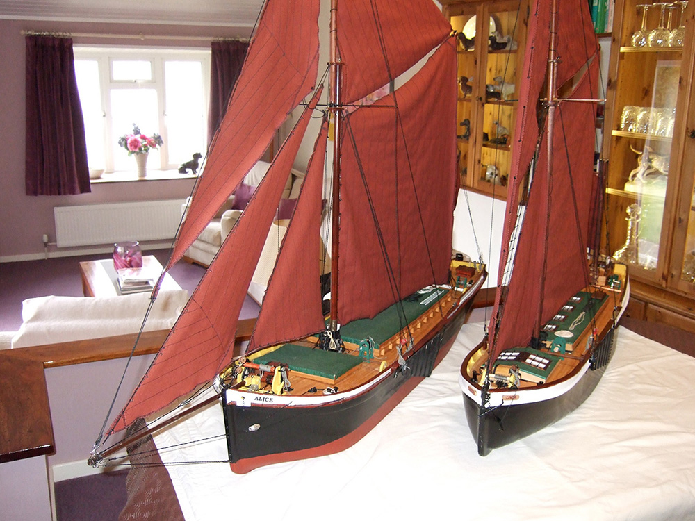
Thames Barge Build - words and pics by Mike
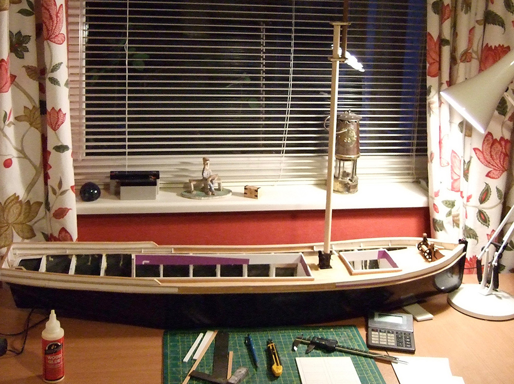
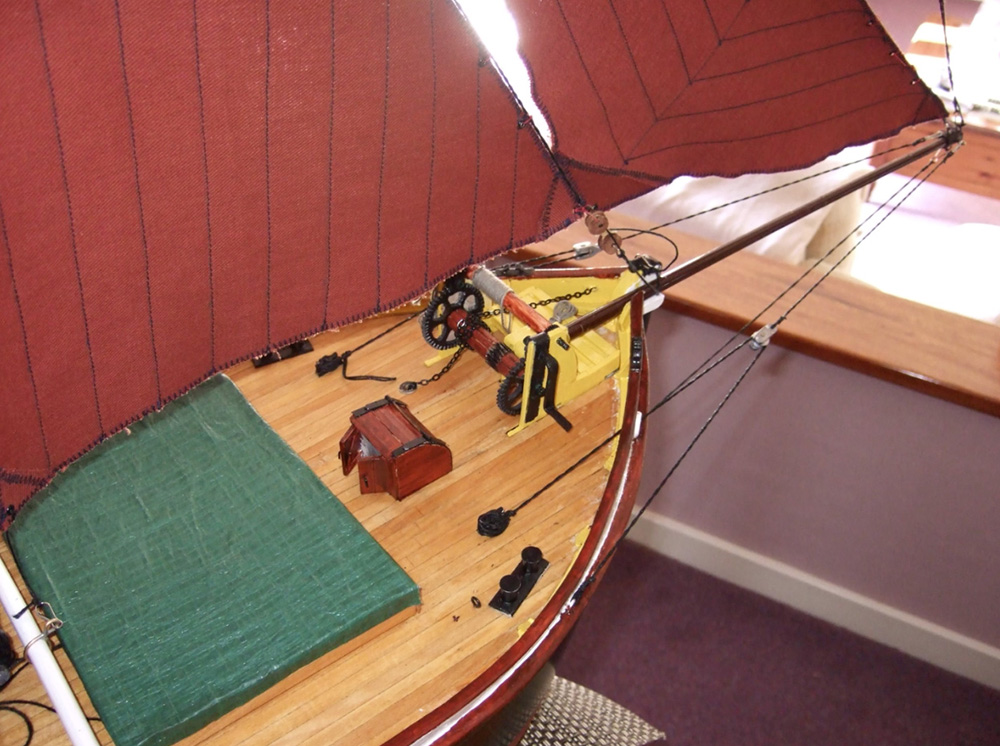
That's it then !! Finished second barge.
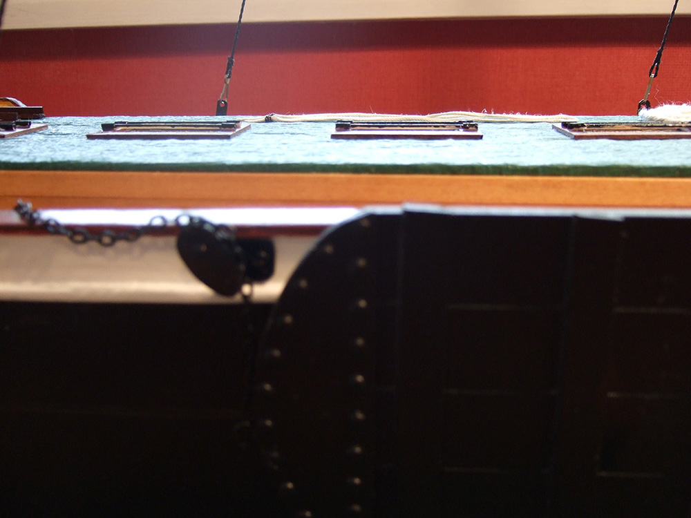
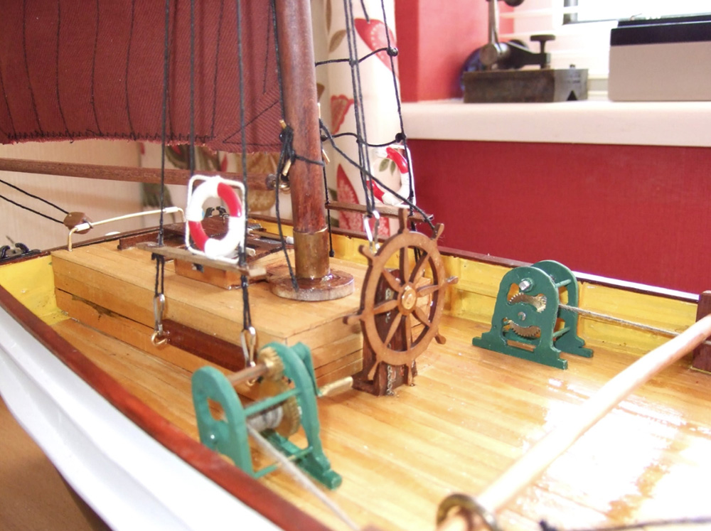
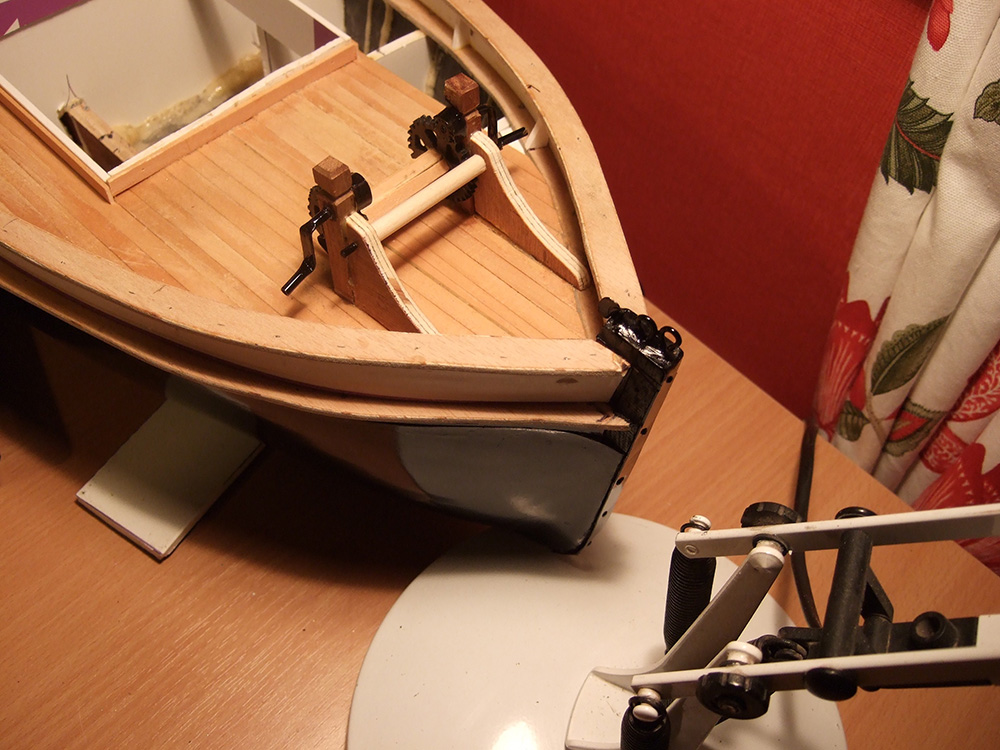
I said I'd build this one from any old bits I found lying around and using only basic simple hand tools. Frames, bulwarks and winches etc are from plastic sheet which is readily available from supermarkets as scrap advertising boards. Decks , hatches and housings etc were made from a bamboo blind. One blind 3ft wide by 6 ft long has done both barges with enough left over to do another two. Masts and booms are hardwood dowel or old cane fishing rods and rigging cord I scrounge from a cobblers stock. With regard to the sails, I bought 1.5 yrds of lightweight canvas. By cutting out paper sail templates and a bit of juggling I managed to make all sails for both barges. I've become somewhat proficient with a sewing machine but they could have been sewn by hand.
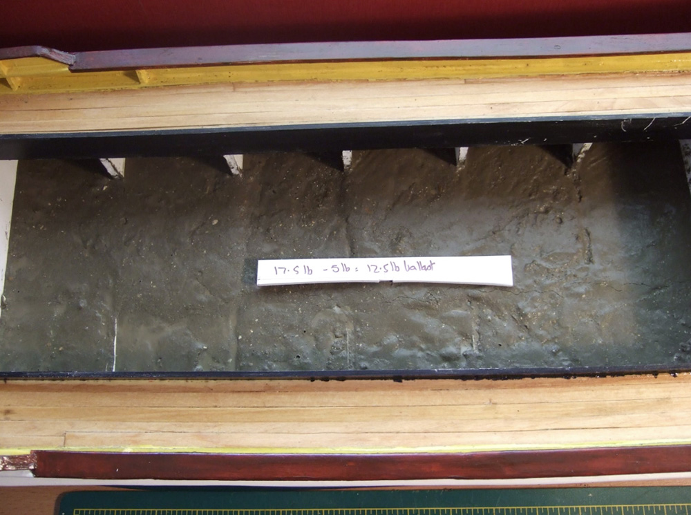
Tools needed were a 12" steel rule, knife with break-off blades, tape measure, junior hacksaw, some small clamps, Thread for alignment. superglue and aliphatic wood glue ( expensive but the best and 200ml will stick and seal a whole boat). Most everything, if not ready to hand, is cheap from the likes of Poundland. (Other shops are available - Ed) Having gained experience from building the first barge to an up-scales set of plans and read an awful lot on barging matters, I concluded that no two barges were identical and, apart from racing where maximum sail area mattered, a bow sprit and flying jib were not really worth the effort required to man and maintain them. Many barges dispensed with them and I did likewise for the second barge. Anyone with a will, if not the immediate skills, can produce a presentable sailing craft. Having said that I've experimented by adding 12.5 lbs of internal concrete ballast below waterline level. Hopefully it will sail OK and dispense with the need for a removable keel. Fingers crossed.
Pictures from Mike's build - click on an image to enlarge
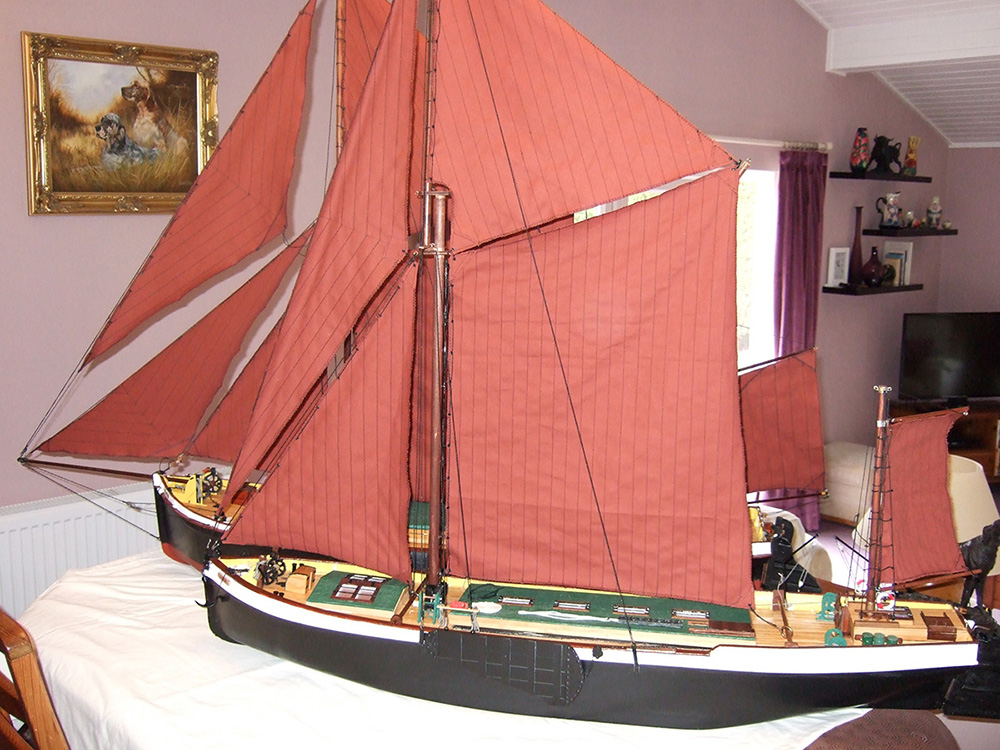
Wild Duck (Blue Teal) built by Tony Dalton from Luton and District Model Boat Club
Reproduced by kind permission of Luton & District MBC.
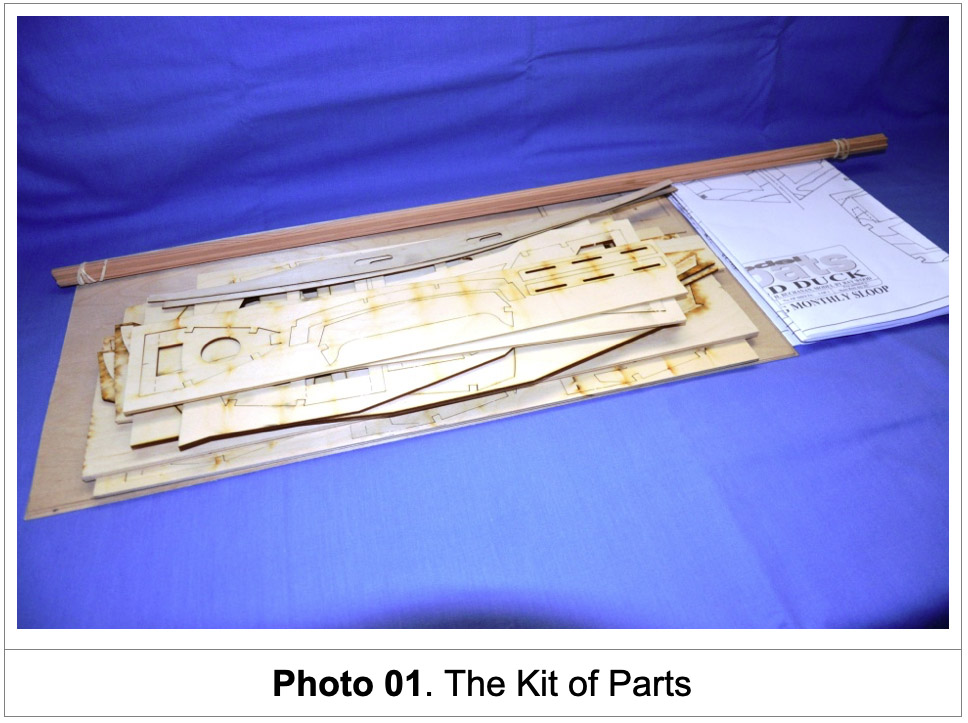
Late in 2021 I was approached by Chris Jackson with a request to build a model yacht. He had come across an article in an old Model Boat Magazine (July 2017) for a small sloop which had been designed and built by Ray Woods, it was called ‘Wild Duck’. After a short discussion and having read the article in Model Boats, I agreed to build it on the bases that Chris would purchase the laser cut wood pack and plans kit from Sarik Hobbies. In the mean time I located the article from my store of Model Boat digital issues and copied it for reference purposes. Being the Christmas period there was a slight delay of a few weeks before I received the kit (January 2022) shown in Photo 01. This allowed me to inspect the wood pack, study the plans and take another look at the article.
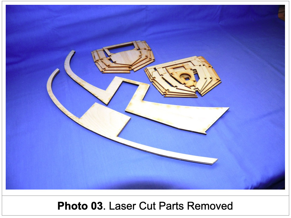
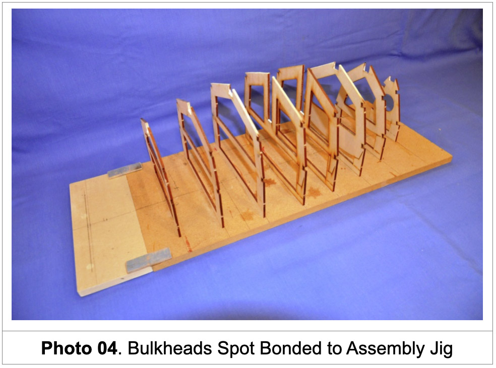
My first job was to construct an assembly jig to support the bulkheads during the hulls construction in accordance with the Ray Woods article this is to ensure that each bulkhead is positioned correctly along the hulls centre line. With the jig assembled it allowed me to proceed with the removal of the bulkheads and the keel from their frames using a Stanley knife to cut the tiny joins left in the laser cut plywood. With all the main bulkheads removed I was now ready to begin assembly. Each bulkhead was positioned up against a guide attached to the jig and spot bonded into position (Photo 04).
The three layers of the keel were bonded together and trial fitted into position between the slots in the bulkheads. Unfortunately the slots in the two aft bulkheads B6 and B8 had not been laser cut wide enough to accept the keel width, requiring them to be modified (increase the width of the keel slots B6 and B8). With the modifications carried out it allowed the keel to be fitted into its required position after some minor trimming of the bulkhead slots. With this completed the aft bulkhead Transom was fitted and glued into position .
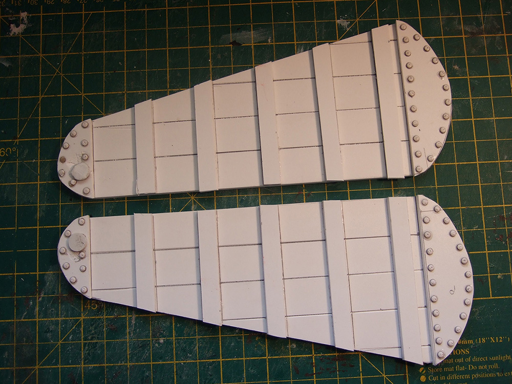
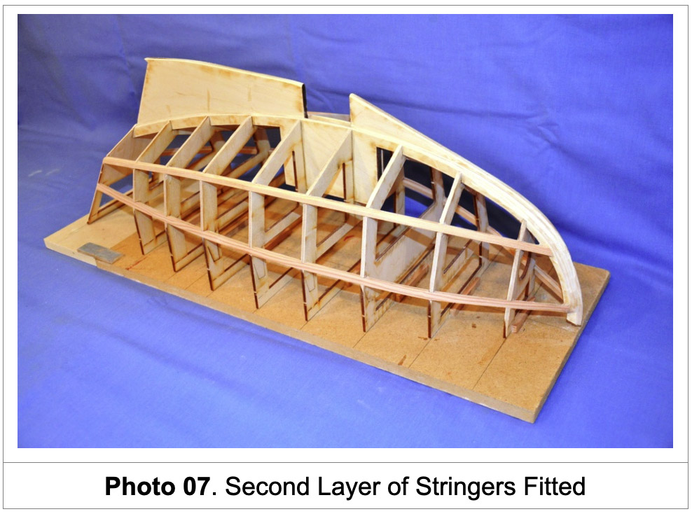
The Chine and Gunwale stringers were next to be fitted, being made up of two layers of 6x3mm thick obechi strips. This required some trimming of the slots in the bulkheads in order for the stringers to sit neatly in position Photo 06 shows the first layer of stringers fitted and glued into place. Photo 07 shows the second layer of stringers formed and glued into position over the first layer, this provides added strength. When all the glue joints had dried the frame work was sanded down to ensure the stringers were level with the edges of the bulkheads and ready to receive the outer skins.
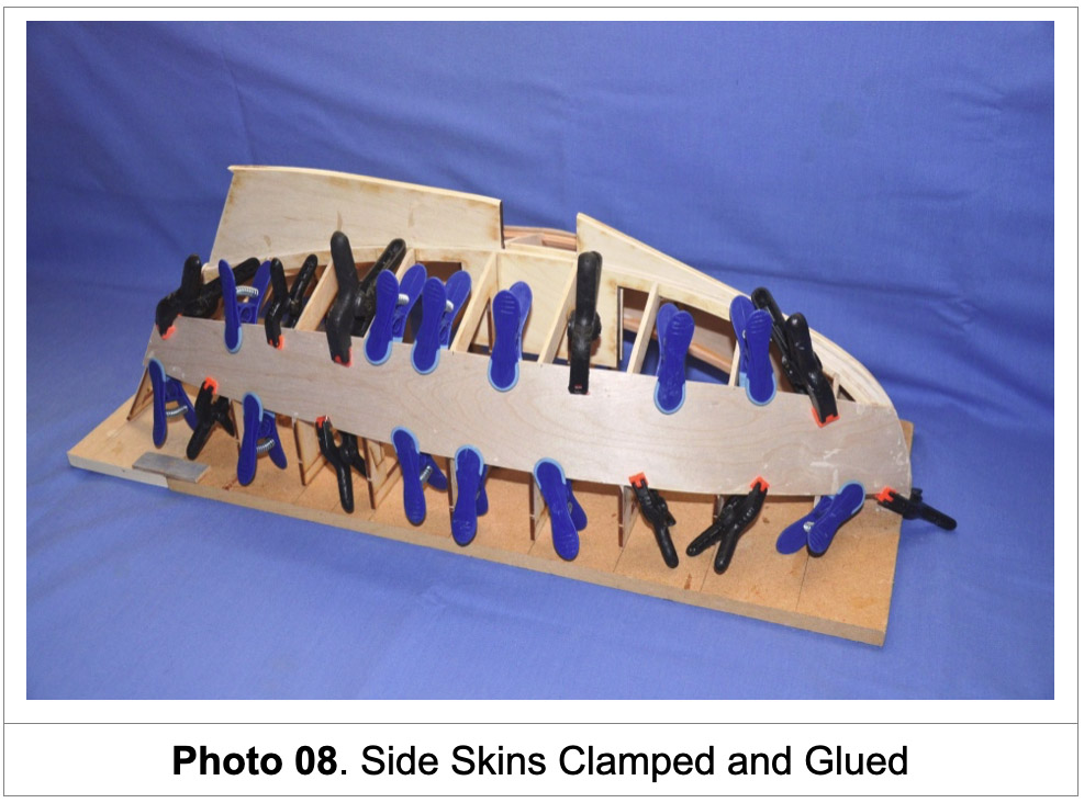
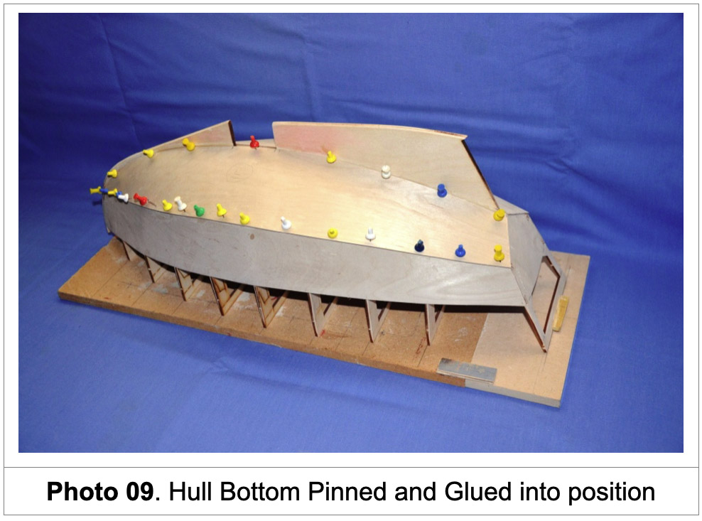
I made templates for the hull’s outer skins using cardboard obtained from cereal packets. Initially cutting the cardboard to the approximate required shape and then placing the card over the hull and marking the card against the shape of the frame using a sharp pencil. Using the card template for the side of the hull, I marked a sheet of 1mm plywood to the required shape and cut it to size using a Stanley knife. The cut sheet was offered up to the hull to verify its correct size and then glued to the hull frame, clamping and pinning it into position. The same procedure was adopted for the other side of the hull

This is a long article, to read the rest download the PDF
YouTube Video Channel...
Don't forget to check out our channel on YouTube to see some of our boats in action... we usually have a new video every couple of weeks.